Introduction
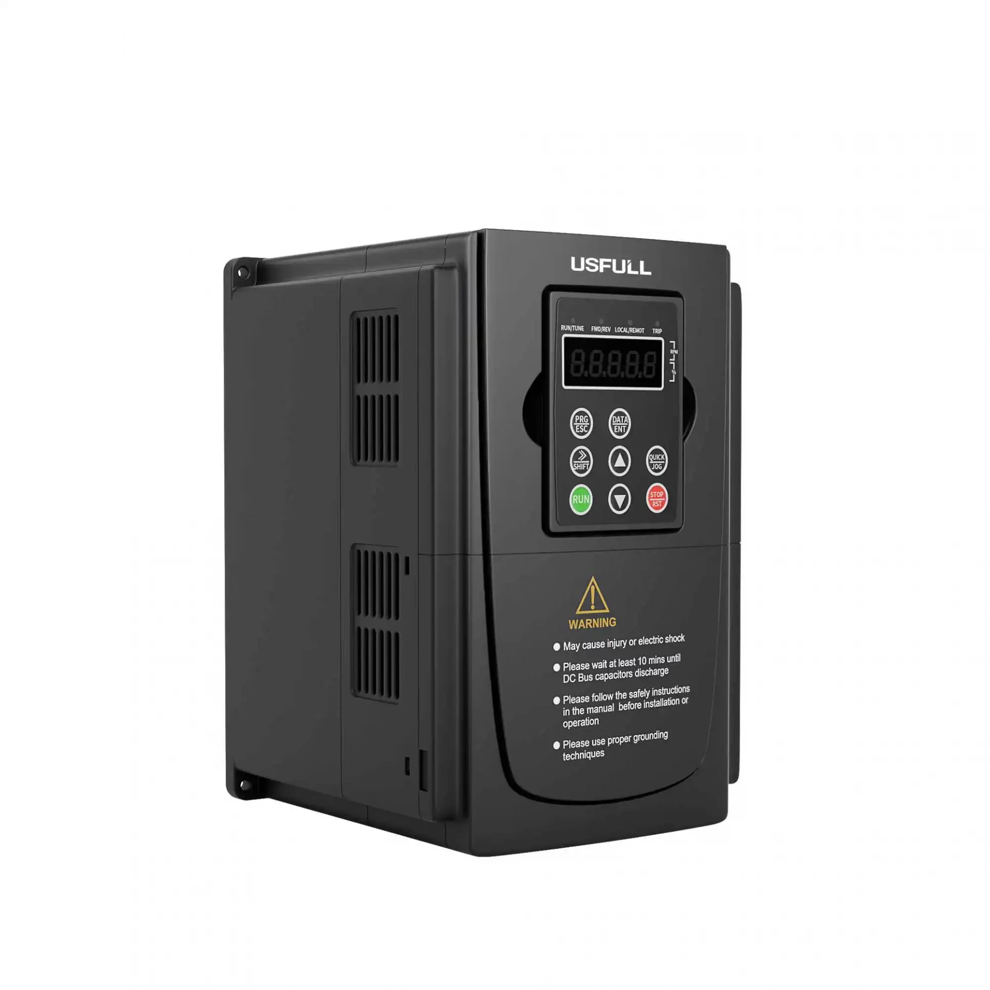
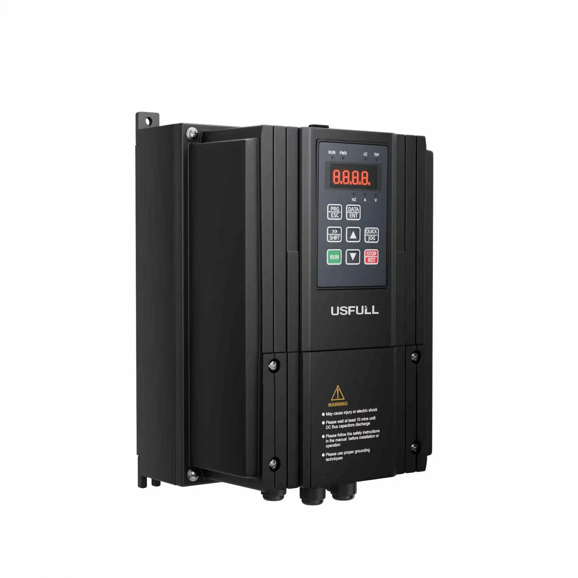
A Variable Frequency Drive (VFD), also referred to as a frequency inverter or variable speed drive, controls the speed of motors by adjusting the frequency and voltage supplied to them. In many industrial applications, a rapid deceleration or sudden stop is required. During such braking processes, the motor transitions from a driving state to a regenerative one, where it generates electrical energy. If this excess energy is not properly managed, it can cause the DC bus voltage to rise, potentially damaging the inverter VFD. To prevent this, a brake resistor is equipped with the VFD to dissipate the regenerated energy in the form of heat. This article discusses why brake resistors are crucial in frequency inverters, the types commonly used, and how to calculate the appropriate resistor values.
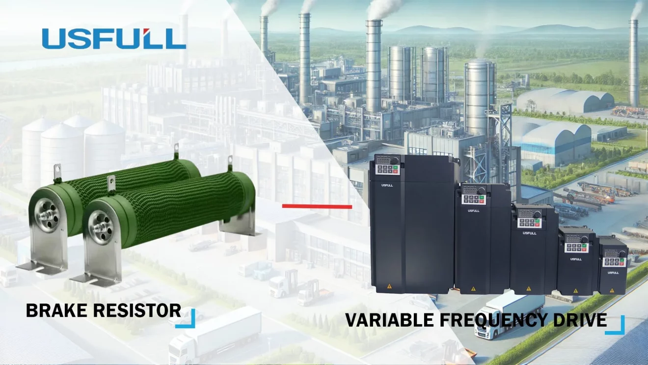
Why Should the Inverter Be Equipped with a Brake Resistor?
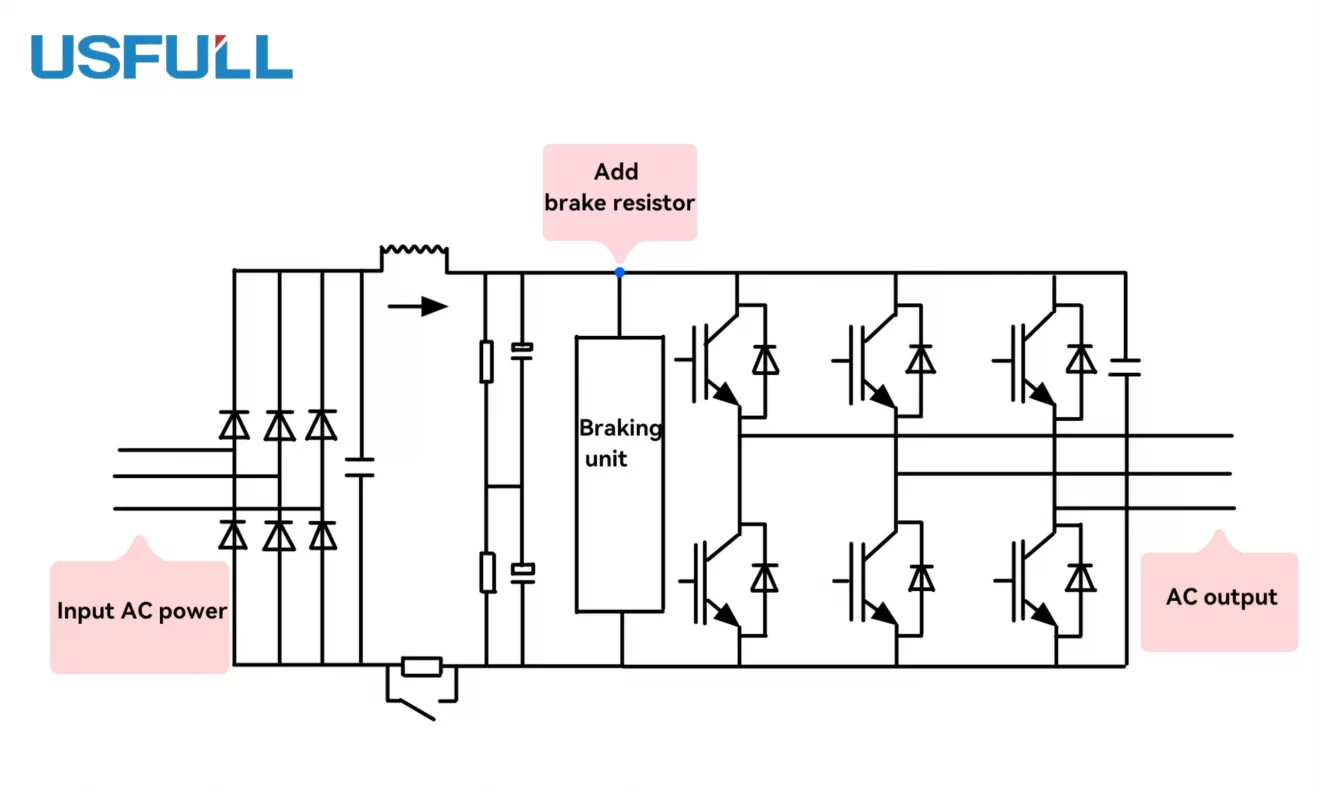
In a variable frequency drive system, motor deceleration and stopping are typically achieved by gradually reducing the output frequency. However, when the frequency decreases, the synchronous speed of the motor’s rotor also drops. Due to mechanical inertia, the rotor speed does not immediately change, causing the motor to transition into a regenerative braking state. In this state, the rotor’s phase current shifts by approximately 180 degrees, converting the motor into a generator. The energy regenerated from braking is sent back to the DC circuit via rectifiers. Since the inverter’s DC bus cannot return energy to the grid, the energy accumulates, causing a rise in the DC voltage, known as “pumped-up voltage.”
The capacitor within the inverter VFD can absorb some of this energy, but it is often insufficient, leading to the need for an external brake resistor. The brake resistor absorbs the excess regenerative energy and dissipates it as heat, ensuring the safe and efficient operation of the variable frequency drive.
Usually Two Types of Resistors Are Used More in Engineering
In engineering applications, two primary types of brake resistors are commonly used in conjunction with variable frequency inverters:
Corrugated Resistors: These resistors feature a vertical corrugated design, which enhances heat dissipation while minimizing parasitic inductance. They are typically coated with high-flame-retardant inorganic materials to protect the resistor wires from aging and extend their service life. Corrugated resistors are highly durable and perform well in dissipating regenerative energy during rapid deceleration, making them suitable for demanding industrial applications.
Aluminum Alloy Resistors: These resistors are encased in aluminum alloy, offering excellent heat dissipation and a compact design. Their robust structure provides high resistance to vibrations, harsh weather, and long-term stability. They are often equipped with heat sinks to enhance thermal performance. Due to their small size, large power capacity, and aesthetic design, aluminum alloy resistors are frequently used in harsh industrial environments.
When a VFD decelerates the motor, the motor transitions to a regenerative state, and the regenerative energy is fed back to the DC bus. The brake resistor, together with a braking unit, detects the rise in DC voltage. When the voltage exceeds a predefined threshold, the braking unit activates and discharges the excess energy through the resistor until the voltage drops to safe levels.
How to Calculate the Resistance of the Brake Resistor Equipped with the Inverter?
Calculating the correct resistance value for the brake resistor is essential to ensure proper braking performance and to prevent damage to the inverter or braking unit. The following steps outline how to determine the resistance and power rating of the brake resistor:
Determine the Required Braking Torque: The braking torque needed during deceleration is a key factor. This torque is related to the motor power and load characteristics. The brake resistor should be selected based on the maximum braking torque required.
Calculate the Brake Resistor’s Resistance: The brake resistor’s resistance value should be chosen to ensure that the braking current Ic flowing through it does not exceed the maximum allowable current of the braking unit. The formula for calculating the brake resistor’s resistance is:

- 800 represents the maximum possible DC voltage in the inverter.
- Icis the maximum allowable current of the braking unit.
Additionally, for motors with different power ratings, the following general guidelines can be used for calculating brake resistor values for 380V series motors:

Calculate the Power Rating of the Brake Resistor: The power rating of the brake resistor depends on the motor power and the braking frequency. A general rule of thumb for calculating the power rating of the resistor is:

- Load percentage is typically 10–15% for general loads and 15–20% for frequent or long-duration braking.
Consider Safety Margins: To ensure long-term stability and prevent overloading, the maximum power rating of the brake resistor should be at least 1.5 times the VFD’s power rating. Additionally, the braking current Is should not exceed the inverter’s rated current Ie.
Conclusion
Equipping a variable frequency drive with the correct brake resistor is crucial for safely managing the regenerative energy produced during deceleration or stopping. Understanding the principles of braking in a frequency inverter system and selecting the appropriate resistor based on resistance and power calculations ensures that the inverter VFD operates efficiently and safely in demanding industrial environments.

